


Technical details
Description, documents, and source code.
Hands-on analog circuit experiment kit
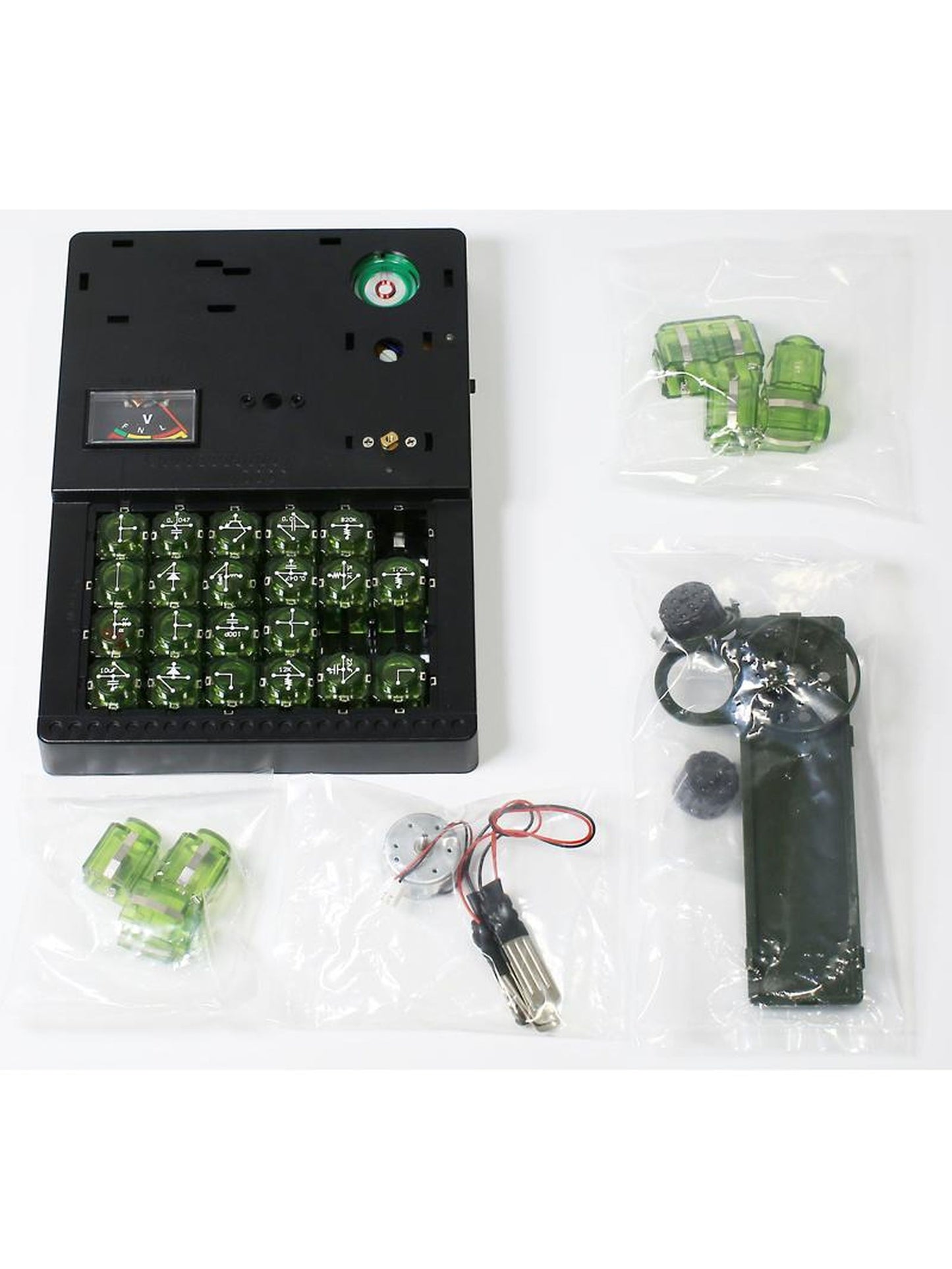
The Analog Circuit Experiment Kit is a hands-on educational model for learning how basic electronic components work in real analog circuits. By combining plug-in circuit modules, learners can build LED, diode, transistor, oscillator, sensor, motor-control, radio, and delay circuits without soldering.
What you can learn
- How current flows through a closed circuit
- Diode directionality and rectification
- Transistor switching and current amplification
- LED brightness control with resistance and transistor base current
- Conductors vs. insulators using test leads
- RC delay behavior with capacitors and resistors
- Oscillation, flashing LEDs, speaker output, and sound/light control
- Photoelectric control, microphone input, motor speed control, and simple radio reception
Included parts
- Main experiment body with module area, meter, power switch, and battery compartment
- Plug-in circuit modules for resistors, capacitors, electrolytic capacitors, diode, LED, transistor, microphone, amplifier, motor, speaker, meter, and connection paths
- Motor, speed fan, speaker cover, volume knob, tuning/select knob, tuning cover, connection leads, screws, and screwdriver
Requires: 3 x AA batteries, not included.
Experiments covered in the manual
- Current and closed-circuit experiment
- Diode directionality and rectification
- Transistor characteristics
- LED brightness control
- Conductor and insulator test
- Sound and light oscillation circuit
- Open-circuit alarm
- Multivibrator oscillator
- Transistor current amplification
- Motor speed control
- Simple radio receiver
- Transistor delay circuit
- Automatic LED night-light circuit
- Light-controlled delay switch
- Voice-controlled flashing LED circuit
- Voice-controlled delay switch
Assembly overview
The kit assembles with the included screws and screwdriver. Install the motor and speed fan, attach the speaker cover, install the volume and tuning knobs, connect the motor plug, set the power switch to OFF, and install three AA batteries before use.
Safety notes
- Adult supervision is recommended, especially for younger learners.
- Read the wiring diagram before each experiment and place every module in the correct position and direction.
- Switch power OFF after experiments.
- Do not connect the leads to household mains power.
- Do not short the power terminals.
- Do not mix old and new batteries or different battery types.
- Non-rechargeable batteries must not be charged; rechargeable batteries should be charged only under adult supervision and removed from the product before charging.